
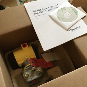
The past few weeks have been incredibly busy. I cannot describe it. But I decided to make some time to try out something non-standard that might save clients some money on their transmitter costs. First off I need to give a shout out to Simark Controls for lending me this new 4102 transmitter so I could do this testing.
The Problem
Traditionally if you are a Floboss customer you would be using their MVS 205 or a Rosemount 3095 transmitter along with an MVS card. However, Emerson recently deprecated both of those transmitters and release a new version called the 4088. Word on the street is that this new 4088 transmitter works fine with their Floboss flow computers and RTUs but it is not as friendly when used with other manufacturers flow computers. So what we are seeing is customers tending to move towards different transmitter brands (Schneider, Foxboro, etc.) for their facility metering.
Now, say you want to standardize on a particular transmitter brand for a field or part of your operation. Not to mention that some transmitters (like the 4102) are generally 10-20% cheaper than the Emerson transmitters. Does the 4102 MVT that you use in your facility work with the FB107 you have in the field? Lets find out.
The Setup
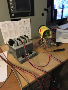
So I have a FB107 on the bench. It contains an MVS card, some I/O cards and is a treat to work with. First off, I wanted to see if a 4102 transmitter could be substituted for a MVS 205, 3095 or 4088 transmitter.
I got my wires out and connected the RS-485 A and B terminals of the 4102 transmitter to the MVS card. Opened up ROC Link, navigated to the MVS Sensor setup pages and asked the first sensor to connect to address 99 (this is the default address of a new 4102). I hit Apply. The MVS lights start to blink; Tx, Rx. I pressed Update. Wow, I got process variables back! Woohoo! Press Update again. Some more blinky lights on the MVS card. Tx, Tx, Tx. Uh oh, the sensor is failed.
Okay, well that was not a completely failed test. It showed that a 4102 transmitter has some similar address mapping to the other transmitters (I am told the process variables are in the same Modbus addresses as a 3095 transmitter). BUT it is not fully compatible with the MVS card and the settings that it looks to access and/or save.
Plan B: I re-wired the transmitter to the RS-485 port of the FB107 CPU. The plan now is to get the values out with regular Modbus.
Note: I did not complete an important step that any field install would need to be compliant and accurate. Once you power up the 4102 transmitter you would need to configure it using the 4000 Series Configurator Software that comes with it. Once configured you would want to ‘calibrate’ or check the zero of the differential pressure, static pressure and temperature using the appropriate methods.
Now that the wires are swapped I need to setup the Floboss.
Step 1 – Configure the RS-485 Port
Click up on the ROC menu and then on Comm Ports.
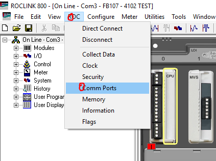
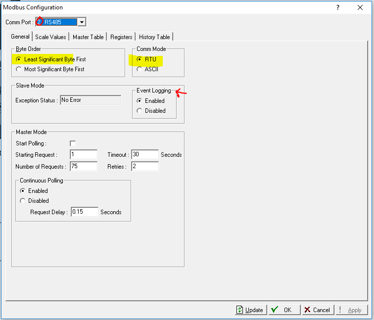
Setup the RS-485 Port. I matched everything up to the DEFAULT settings of the 4102 transmitter. Make sure you select Modbus Master or nothing will happen. 🙂
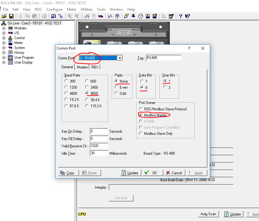
Click OK and your RS-485 port will be set.
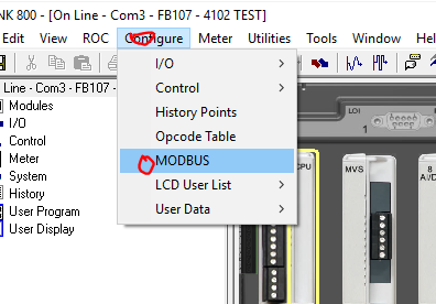
Step 2 – Configure the MODBUS Tables
Click up on the Configure Menu and then on MODBUS.
Click over to the right comm port (RS485) and then set it up like below. Continuous polling isn’t enabled by default. You will want that turned on.
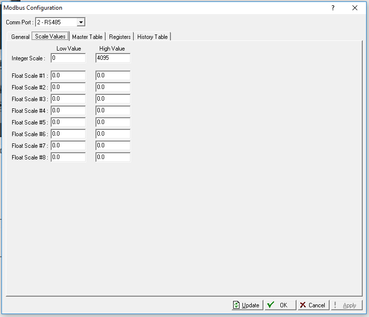
Leave the Scale Values Tab at default.
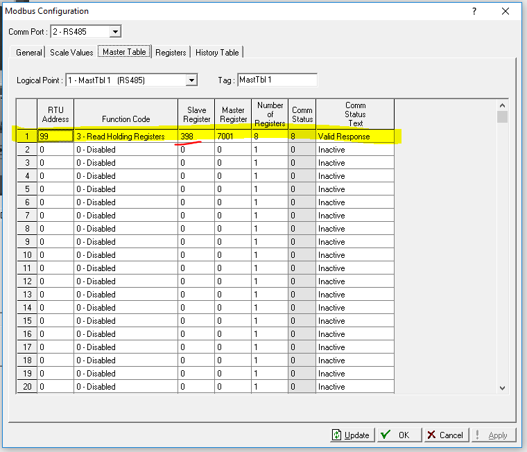
Setup your Master commands. Luckily all the process variables are in a continuous set of addresses in the 4102 MVT.
Read Holding Registers (FC3)
Start at Slave address 398 (40399) and get 8 registers.
Put it into address 7001 in the Floboss.
This has been communicating for a bit so I have a Valid Response status back. Yours will not say this until you have established communications. Click Apply and then Update at the bottom to refresh the screen.
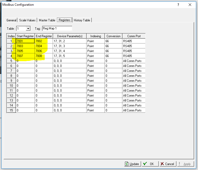
Now setup the Registers tab. Now I am not the greatest Floboss guy, so this Modbus mapping is new to me. But as I understand it, you need to Map the Master modbus registers back into points in the Floboss. So I started at address 7001 and mapped my 4102 read points back to Soft Points in the Floboss. I am reading four floats.
Also… note that I put my numbers into Soft Point Table #32. Type = 17, Logical = 31, Parameters 2 thru 5 (the first four floats).
Modbus Conversion – I think I need to write another article just on Floboss Modbus. I plan to cover the different conversions there. For now, I just know that 66 works for this purpose.
Click Apply or OK and close out the MODBUS configuration. It will be applied.
At this point you should see blinky lights on your RS-485 port on the FB107. It should be steady. IF you only see a Tx light you might need to swap your A and B wires. Luckily in this case it appears that the 4102 and the Floboss have the same polarity. A to A and B to B. Some manufacturers mix up the polarity on A and B.
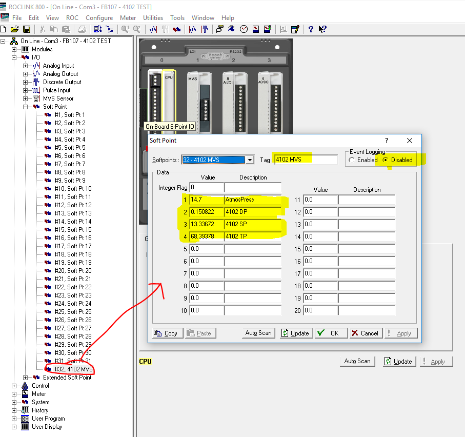
Step 3 – Check the Soft Point Table and Add some labels.
So now navigate to I/O->Soft Point->#32. You should see values coming in from your 4102. We are reading back four values:
- Atmospheric Pressure (configured using 4000 series configurator)
- Differential Pressure
- Static Pressure (Absolute)
- Temperature
The default out of box configuration is Imperial units (inH2O, psi, deg F for DP, SP and TP respectively). If you configure the transmitter you can change the units. I would recommend sticking with the default for Imperial units installations and use kPa, kPaa (or kPag), and deg C for metric installations; again DP, SP and TP respectively.
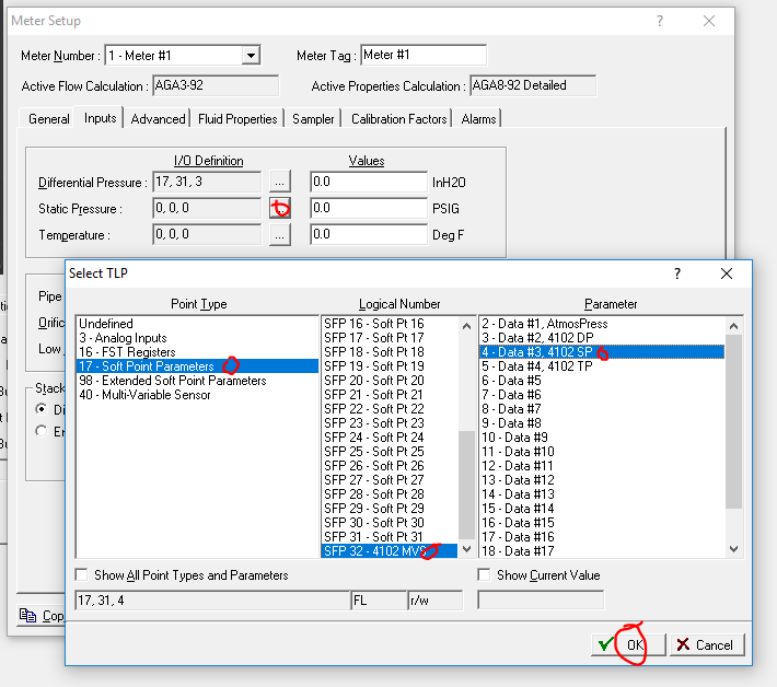
Step 4 – Configure Your Meter Run to Use the 4102 as an Input Source
Now navigate over to the Meter Setup. Open up setup for the meter you want this sensor to be connected to.
Click over to the Inputs tab and select the three soft points that match to your transmitter readings. Note the units that the Meter Run is expecting. You should try to match the transmitter units to the same.
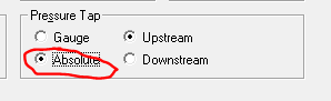
I am leaving out most of the meter configuration because you should already know how to do that. The only other setting I wanted to bring up is the Atmospheric vs Gauge pressure setting. 4102 transmitters are absolute transmitters. You should try to match your meter configuration to the transmitter. BUT if this causes issues with calibration (if you don’t have equipment to calibrate absolute pressure) you should configure the transmitter to send you a gauge pressure instead. This should make the transmitter ‘correct’ its absolute pressure down by subtracting the local atmospheric pressure (also configured in the transmitter). Make the setting in the Floboss match. Otherwise you will either not correct or double correct the pressure for the local atmospheric.
FYI – The static pressure is always read from the high side of the manifold unless it is installed backwards. This setting is on the Advanced tab of the Meter Configuration.
Finished
And now I have a 4102 transmitter feeding differential pressure, static pressure and temperature into my Floboss.
Disclaimer: I am not receiving a commission for this R&D work. This is for the benefit of the industry and to help find innovative, easy solutions to client problems. If you are an end user or vendor who would like to have products or new setups tested and tried, please send me a message on LinkedIn. If you want to contribute articles to the blog just shoot me a message on LinkedIn.