Its been a good month. I recently did some ClearSCADA training and apparently I might be one of a select few who has used the DNP3 features on SCADAPack in Western Canada. If you have also used DNP3 for your SCADA project, feel free to drop me a line, correct any non-sense, or otherwise comment below. 🙂
Some terminology to get out of the way…
Master – This is a SCADA host, data concentrator, or DNP3 routing device. It could be a SCADAPack. It could be ClearSCADA. It NEEDS a DNP3 address (it acts on the network another node).
RTU/Outstation – This is a ‘slave’ or reporting device. Its typically the end of the network and produces data or accepts controls.
Change Events/Events – These are produced when a point or input changes in the RTU. There are configuration settings in the RTU that define how ‘sensitive’ it will be to changes. Events are stored with time stamps (logged, yay!) so that they can be reported to the SCADA host or Master as a complete record; Time + Data.
Unsolicited Event – This occurs when an event is sent to a master station. The RTU has configuration settings that dictate when it should send events up to the Master Station/ClearSCADA.
Event Buffer – These are storage ‘containers’ in memory for storing events.
OK. So you have your SCADAPack. You have ClearSCADA with the DNP3 driver installed. You need to establish communications. Lets get the SCADAPack setup first. I will post the ClearSCADA setup in another article. I am using Telepace. Configuration using Realflo and Isagraf should be similar. I am also assuming your communications path is a network or Ethernet path.
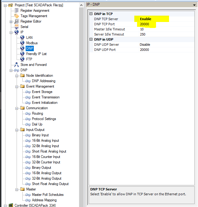
- Set your DNP3 Network Settings. Click over in the Project tree to IP->DNP.
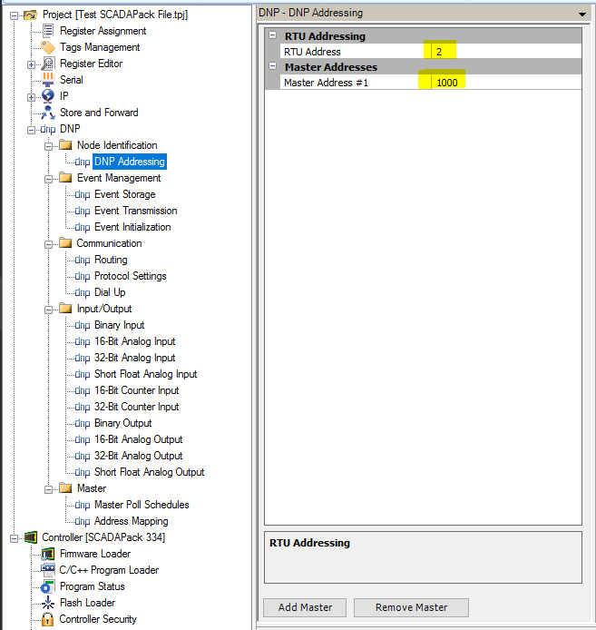
- Set your RTU’s DNP3 address. Also enter the master address(es) this RTU should report to.
** Interesting and Important Tidbit: With DNP3 EVERY node on the network has an address (including the master stations, like SCADA hosts). This allows the RTU’s to forward change events to the proper master using report on exception (unsolicited events in DNP3 terminology). Here in my example, my master is at address 1000. We will be defining a network ‘route’ to the master later.
** NOTE: Do not define more masters than you have available. IF THE MASTER ADDRESS IS SETUP INCORRECTLY UNSOLICITED MESSAGES WILL NOT WORK.
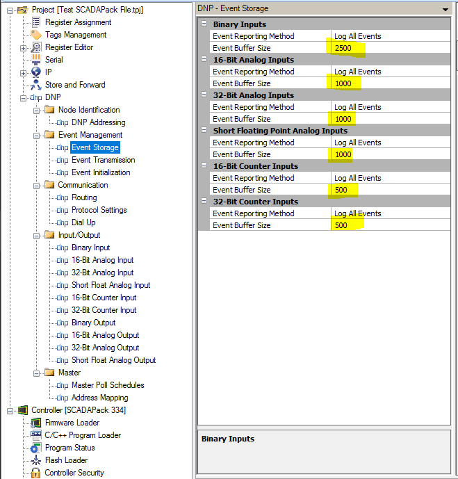
- Set the Event Storage parameters and Buffer Sizes.
** NOTE: Make sure you set large enough buffers for your data. If they are too small you will potentially lose data if communications is lost to the RTU. There is a balance between how many change events you generate in the I/O setup, how often you send unsolicited messages, and how often the Master polls this RTU for data (time between polls). The settings below are likely ‘sane’ defaults, but mileage may vary.
- Configure the Event Transmission Settings. This is WHEN the RTU should send unsolicited events. The configuration is either/or… so if I have had an event for 5 seconds OR if I have 1 event (if you look at the Class 1 settings).
** NOTE: There is a balance here between how often ClearSCADA or the master RTU polls this slave and how quickly/often you send unsolicited events, particularly with serial channels. To keep the telemetry network from being overloaded try to send unsolicited events quickly and often, while polling less frequently with the host. Alternatively, you can poll a little more frequently with the host but really limit your unsolicited messages to critical events only (this behaves more like traditional SCADA systems). That said, if you send individual events all the time, you do not gain any efficiency in your network transmissions. Try to ‘bundle up’ several events together and send them as a group, instead of individually. This will reduce your protocol overhead greatly while leaving the telemetry more open for other RTU’s to talk.
** Suggested Settings are below. I reserve the right to change these without notice if I find new settings work better. 😉
Class 1 = Critical Events, these need to be sent ASAP. Only limit to a few critical points/inputs; compressor down; low flow; etc. Be stingy.
Class 2 = Regular data, held for 5 minutes, or 100 events. Likely most regular operations data and alarms.
Class 3 = Less important data, held for 15 minutes, or 100 events. IE. Data logged data that isn’t immediately used/consumed by operations.
Class 0 = These events are never sent unsolicited, but are stored for later retrieval. 🙂

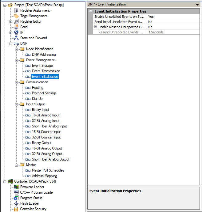
- Configure Event Initialization (leave at default). I still need to play with a few of these settings to understand what they do and how they might affect communications. These are the Telepace default settings.
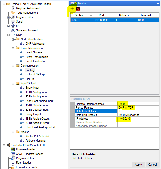
- Configure DNP3 Routing. This is an important step. This tells the RTU which port and address the master station is at. This allows it to send unsolicited messages.
** I believe you can also define remote slaves in this list too, essentially making this RTU a store and forward unit in the network. It should listen for its own messages as well as the remote slaves in this list. I haven’t played with that type of setup yet but I would like to try it out sometime.
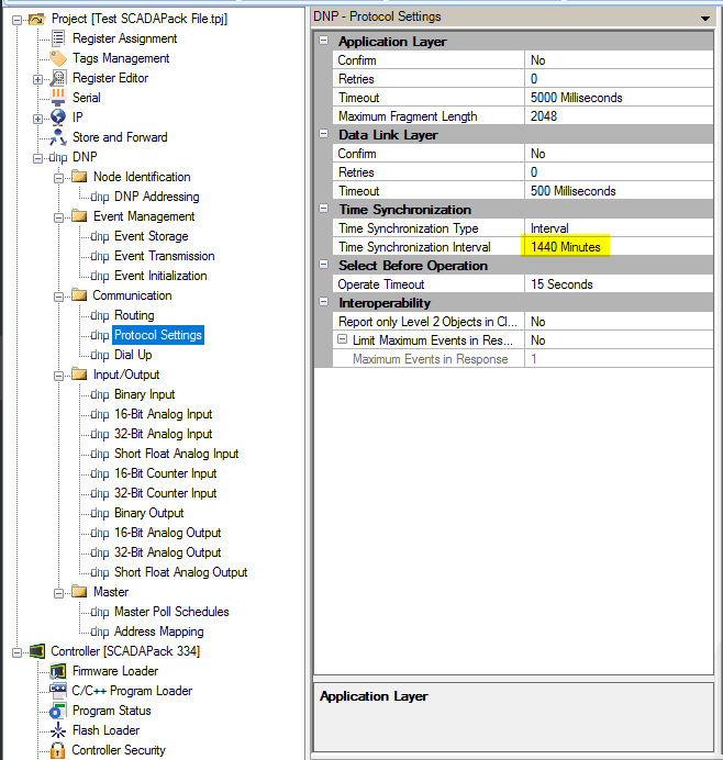
- Set the DNP3 Protocol Settings. These are mostly default, I only tweaked the clock-sync setting to sync up once per day. The Telepace Help file indicates that Application Layer and Data Link Layer confirmations are not needed on Ethernet or hard-wired connections. These are used to ‘confirm’ that a message reached its destination. So if an unsolicited message is sent on a serial radio to a master the master will reply back with ‘Yup I got it’. If the RTU does not get confirmation back it will retry until it does (just in case another RTU was talking at the same time, or the radio signal didn’t get thru).
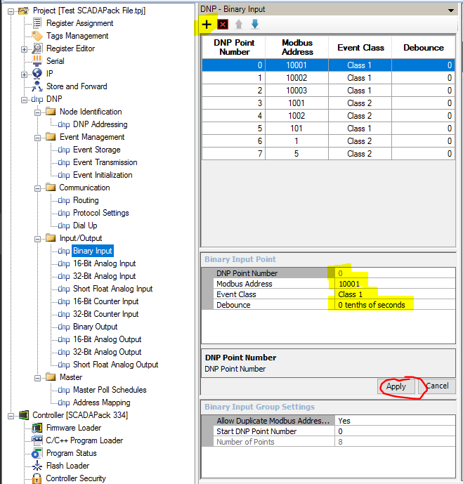
- Configure some DNP3 Points. Binary Inputs. Fairly self explanatory. Binary (discrete/digital) inputs have a debounce setting, so the change would have to stay changed for a period of time for the event to be recorded. Note that some of these are Class 1 points and some are Class 2 points.
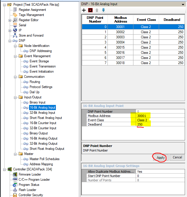
- Configure some DNP3 Points. Analog Inputs. Again fairly self explanatory. The Deadband tells the RTU how much the analog value needs to change before it records an event.
** NOTE: Setting the Deadband seems like more art than science. Depending on the noise coming from your analog input/value you may need to adjust the deadband up/down to either get the resolution you need or to filter out the noise in the signal. We noticed in real-world applications that Tubing/Casing pressures require a much higher deadband (200+kPa or 30+psi) unless there is some dampening on the input (slight averaging helps smooth out the ‘choppiness’ of the pressure signal). IF you record too many events due to a tight deadband you could lose data by filling the event buffers or overload your network by sending too many unsolicited events. You have been warned… the proper configuration of these points IS important.
That is it for basic SCADAPack DNP3 configuration. Check back in a bit and I should have some information about the ClearSCADA configuration that matches up with the SCADAPack posted as well.